
‘Irrigo’ stands for ‘Irrigation on the Go’. Last year, as part of my summer project, our team created this device.
Introduction
Imagine this. You have a trip planned. All bags are packed. But what about your plants? It’s the middle of summer – they will dry up. You could give your neighbours a set of keys to water your plants. But is it worth the trouble? What if you need updates? Our device offers answers to all these questions.
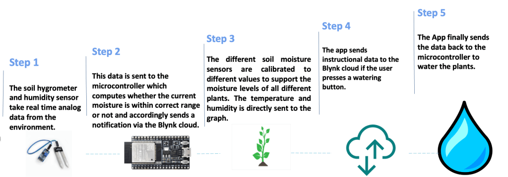
This device waters the user’s plants from any part of the world using an app. The app waters the plants based on the moisture level needed and also monitors the humidity and temperature of the environment.
How it works
Our app offers two possibilities. The first is to automatically water plants without any human interaction. The second option is that the app sends a notification every time the moisture level of the soil dips below the required level. This mode is useful for users who wish to stay updated about their plants.
If the user opts for the notification system, they can water their plants with a simple press of a button.
The App
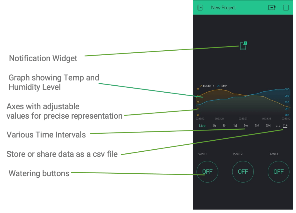
We used a platform called ‘Blynk’ to create the app. ‘Blynk’ is a platform that lends users its servers to create interactive apps for IoT projects. We did try to create an app independently, but we ended up with a crappy HTML page on an obscure URL. ‘Blynk’ is pretty standard; its libraries are open source. Additionally, it was already taking care of the design part, so we could focus on the code.
Here is a breakdown of the app:
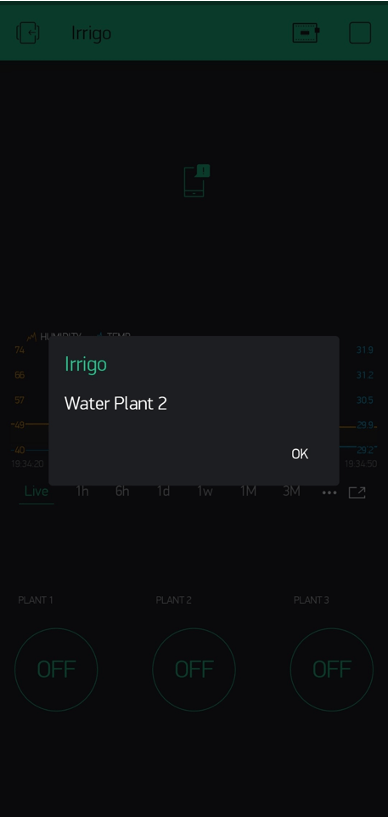
And here is how the in-app notifications look like. We also offer email and SMS notifications.
The Hardware
We used the NodeMCU ESP32 as the microcontroller. Initially we tried using the ESP8266. It’s basically a lower version of the ESP32. We opted for the latter because it had many more GPIOs along with bluetooth functionality and a faster processor.
The main sensor we used was a standard water moisture sensor. There are 2 models available. One has 1024 analog output levels while the other one has 4096 analog output levels. We used the second one in our prototype because that meant we could get more precise values. We coded a program to read and convert the analog outputs into a moisture percentage.
We used a humidity and temperature sensor for the secondary data collection. The MCU we used already had these inbuilt but we could not figure out how to program them.
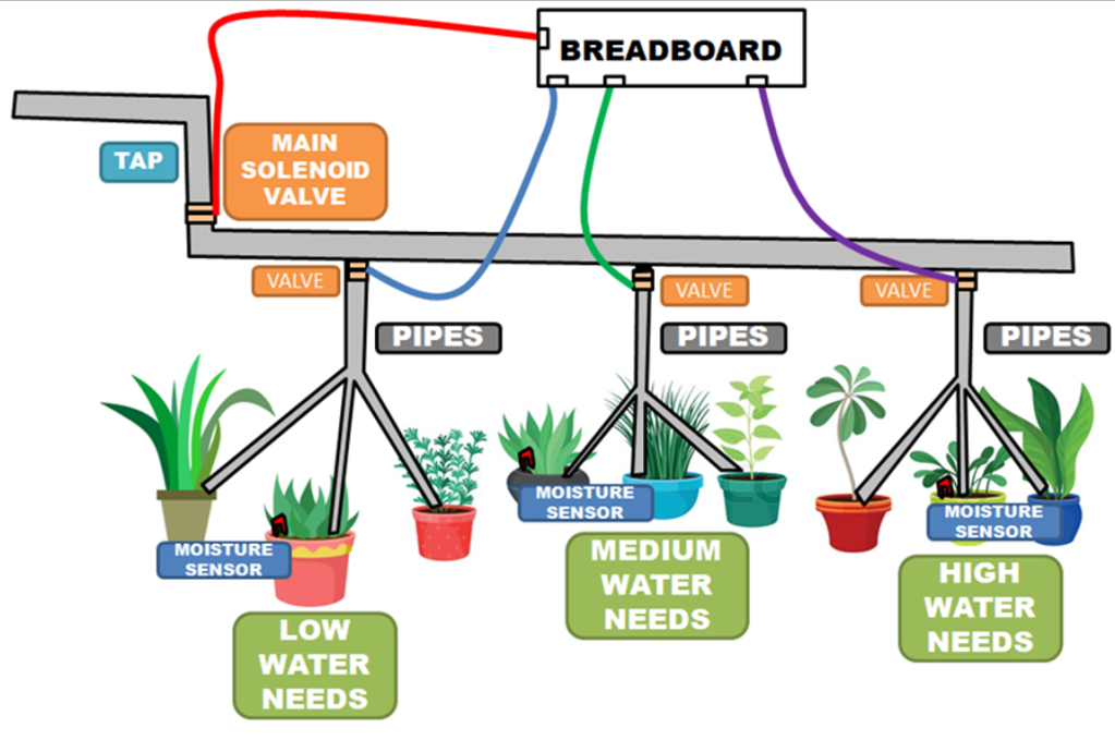
For watering we used a couple of solenoid pumps and and relays. We needed to use a relay because the output power of the MCU was significantly lower than the input needed by the pumps. So we hooked up additional 9V batteries to the pumps using relays that were powered by the MCU.
All of this was connected to a breadboard using male-to-male connectors.

The Setup
In our prototype, the pumps are submerged in water in a big vessel. We have another design where the whole project is connected to a water output using a solenoid valve that is also controlled by the app. This cuts down the effort of filling up the water reservoir.
Pictures


All of this fits neatly into one box.

Conclusion
This was a very fun and educational project to do. It got frustrating at times when we couldn’t figure out some bugs in our code. We spent the first week of this project trying to figure out why none of the libraries we had installed were showing up in the editor. Two of the elements we ordered turned out to be faulty that wasted a lot of time.
We cross referenced product datasheets and pin-outs hundreds of times and then went on other sites to understand what the datasheets actually meant.
But over time we developed ways to become more efficient. For instance, we wrote some sample codes and made a simple setup using an Arduino UNO to test all elements before using them for our project.
Now, on a personal note.
I learnt a lot of coding. I often have trouble completing coding courses and projects because I see nothing play out. Printing lists on a python console just isn’t fun for me. I think that’s because I’m not advanced enough at python to do more complicated projects, but that is a separate story. Seeing the code play out in real life through moving parts is absolutely amazing. How you know the relay will click in two seconds and how the sensor will beep in another three.
By IoT standards, this isn’t a very complicated project. I struggled at very beginner stuff including at turning my board on, but that’s what made it fun.
The designing part was great too. I learnt some photoshop basics while designing the ‘IRRIGO’ logo and the presentation graphics.
This project also kept me occupied in the middle of the COVID-19 pandemic, and I’m grateful for that.
Appendix
This post was a log on the experience on making this project rather than an in-depth discussion of its features. If anybody wishes to read our project report, I would be happy to share it on demand. Attached is a list of some of the important datasheets and sites the team referenced.
Thank you for making it to the end of such a long post. Stay positive and test negative!

Very nice👌🏻👌🏻 The schematic diagram is so extraordinarily beautiful
LikeLike
Nice beta👍🏼
LikeLike