This semester, I took a class on Origami Engineering. Taught by Prof. Paulino in the Civil Engineering Department, it is a class that aims to teach students state-of-art concepts and algorithms to design and analyze origami structures, while also teaching them basics of differential geometry through origami principles. It is one of the best classes I’ve ever taken, and I loved how I could do a very ECE-y project for our final (thank you to my team and TAs for making this possible!).
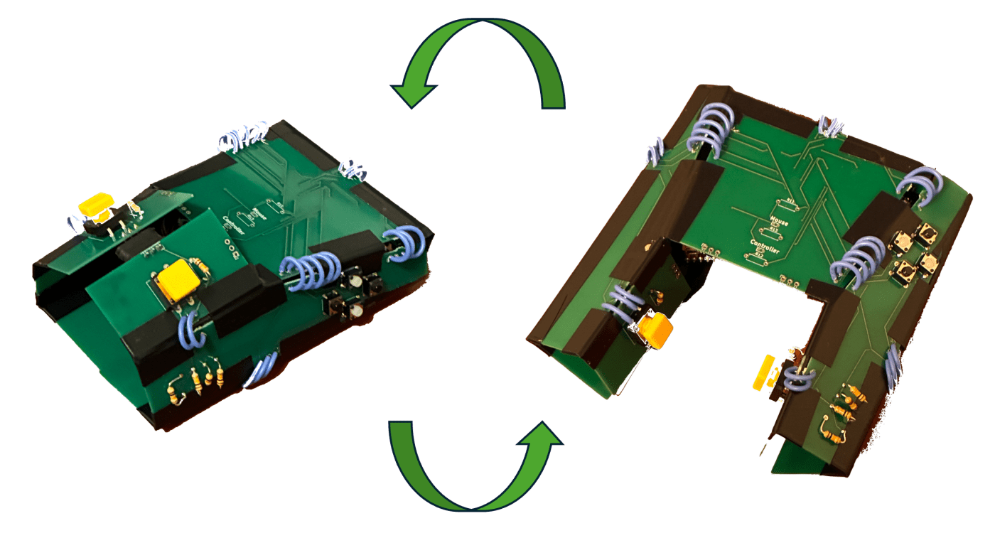
For the final project for this class, my team and I built a reconfigurable mouse-controller. It is a foldable printed circuit board (PCB) that we designed ourselves, that serves as a single origami pattern that can be folded into either a computer mouse or a gaming controller.

The device supports three configuration states:
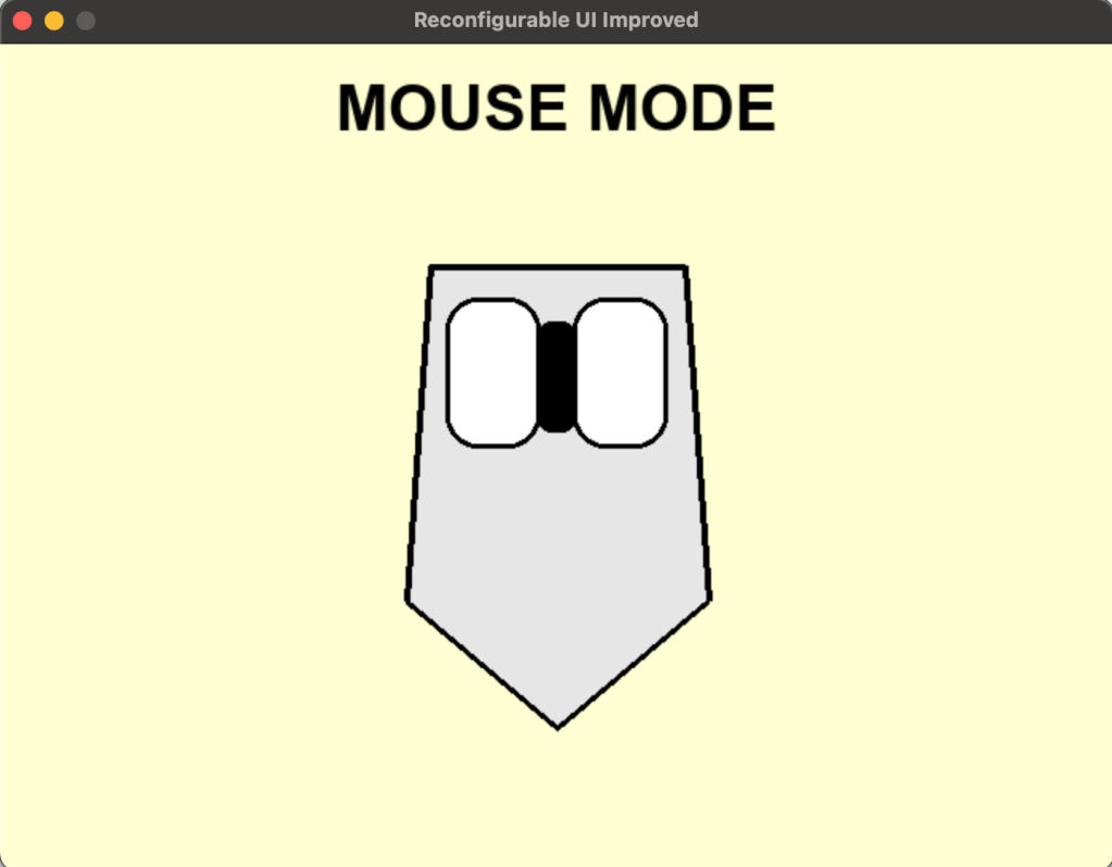
- Mouse mode:
- Two buttons function as left- and right-click.
- Four additional buttons act as webpage navigation controls.
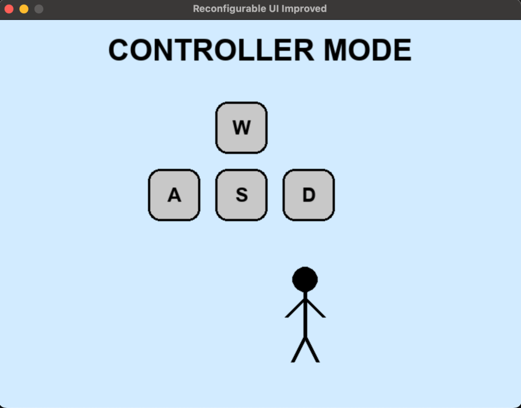
- Controller mode:
- The same six buttons are repurposed to function as W/A/S/D movement controls and drift/action inputs.
- Intermediate:
- The device must not function as either a mouse or a controller.
- All button presses are ignored until a valid configuration is reached.
Throughout the class, we learned about origami structures that could be deployed in multiple different configurations. External forces (for example, applied mechanical loads) or internal forces (such as temperature-dependent actuation) allow these structures to morph from one configuration to another. We found, however, that the literature on self-sensing was very limited. In other words, there is a lot of work on how we can move a structure from one configuration to another through some observer-controlled stimulus, but not much work on how these structures can figure out what configuration they have been put in, and then change their behaviour based on that knowledge.
In our project, for instance, the mouse-mode would require only the left and right clicks to function, and the four other buttons to either serve as shortcut buttons or be ignored. The controller-mode, on the other hand, would require all six buttons to be active and mapped differently, with behaviour changing depending on the detected configuration of the structure.
We found a thesis written in 2013 by Yoav Sterman titled “Folding Circuit Boards into Electronic Products”. It was a spectacular thesis to come across because it introduced me to the idea of using PCBs as a medium for Origami. In this thesis, Dr. Sterman talked about a version of this built using a flexible PCB where the different panels connected to one another using magnets, and configuration was detected by counting the number of panels connected, or in a later version, by checking for connectivity at specific edges. We wanted to build a version that offered more robustness to the intermediate state (a counting approach fails in scenarios where both valid confugurations have the same number of mating edges, or if an intermediate configuration has the same number of mated edges as a valid configuration; the second approach recognises any intermediate configuration as valid as long as a specific connection is made). Additionally, we wanted a version that has been created using rigid PCBs because, having worked with flex-PCBs for my independent research project this semester, I knew it wouldn’t provide the rigidity we expect from computer mice or gaming controllers. We also wanted a more general approach to assign magnetic poles to each edge to ensure we never ended up with repelling poles at edges that needed to connect.
I started with attempting to figure out a new self-sensing approach. The issue came down to being able to figure out which edge connects to which specific edge. The first idea was to use RFID, but I wasn’t sure how I would get the form factor down to the level I needed it at. I also just didn’t want to deal with 5+ RFID tags being dealt with on the same SPI bus. My second idea was to use a specific resistance to ID each edge. There are some “Sense” edges, and some “ID” edges. When joined together, a “Sense” and “ID” edge would connect a 10k base resistor to an ID resistor and form a voltage divider. An ADC would measure the voltage between them, and then based on which ID resistor connected to our base resistor, the voltage would change, and we would be able to infer which edge would be connected to which.
I breadboarded this using very high precision resistors, and it worked really well. My breadboard setup just involved some jumpers connected to the relevant ADC ports or high/low voltage levels, and I simulated an edge joining by touching my “Sense” jumper with my “ID” jumper.
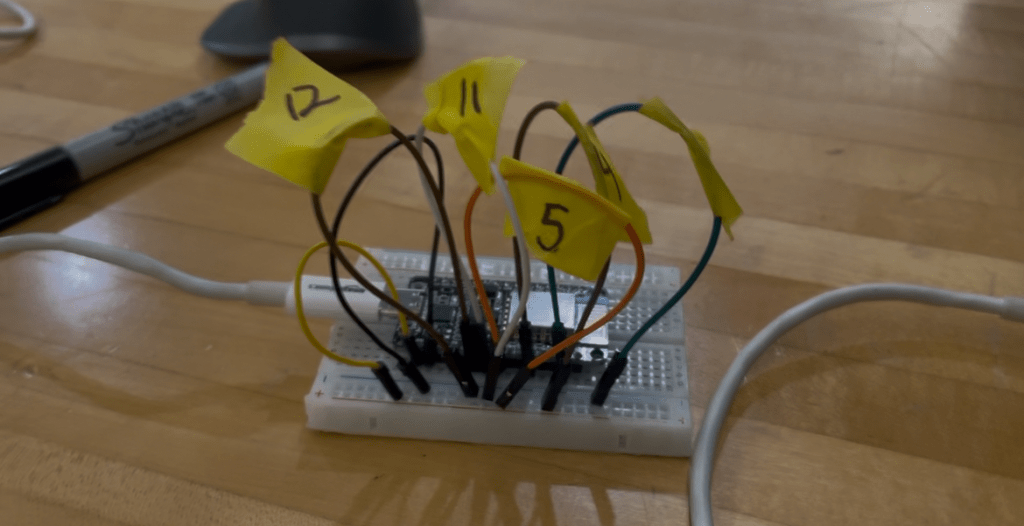
My second idea was much simpler; each “ID” edge would be connected either to a HIGH or LOW logic level so that different configurations have a distinct “voltage signature”. This signature was continuously polled, and if it was what was required, a valid configuration was detected.
Upon breadboarding, this design also worked really well.
I also came up with a graph-theoretic approach to representing the different configurations as a graph, and used that to make the magnetic and logic-level / resistor ID and “sense” assignments. This first gives us a concrete way of making magnetic assignments that scales to much bigger, more complex designs, and second provides robustness to the intermediate state.
On the firmware side, we wrote a bare-bones program to detect the current configuration of the structure and switch behavior accordingly. The microcontroller first infers whether the device is in mouse-mode or controller-mode based on the sensed configuration, and then listens for button events. We printed the detected mode along with the button that was pressed via serial (for example, mouse + left, mouse + right, or controller + W) to verify that configuration sensing and input mapping were working correctly.
While I did design the PCB for the resistor ID design, I ended up just sending the discrete version to fab, just because there were issues with ordering components, and the discrete version entailed dealing with fewer components.
To be able to manufacture our design using rigid PCBs, we broke it up into separate panels which we connected using wires that served both as electrical connections and as hinges that allowed these rigid panels to bend where necessary. My teammates Courtney and Tamyca worked on the mechanical design and created the 3D renders of the origami pattern that guided this panelization and hinge layout. Further, we used magnetic pogo pins (similar to those used in Mac chargers!) for our magnetic connection.


My teammate Vibha created a python-based visualiser that via serial snooping, displayed which configuration/action we were in.

This project was honestly just a blast to work on. It was a really fun way to explore what reconfigurable, origami-inspired hardware can look like when you mix mechanics, sensing, and logic instead of treating them as totally separate things. Seeing a physical object figure out what configuration it’s in and then change its behavior because of that felt very cool and very tangible in a way that a lot of projects don’t.
I especially loved working through the electrical side end-to-end – from thinking about how to sense configurations, to drawing the schematic, to laying out the PCB – particularly since there wasn’t a ton of prior work to copy from. It was also really satisfying to see stuff from a theoretical CS class last semester actually show up in a real build through the graph-based configuration and pole assignment logic. If I keep pushing this project forward, I’d love to fabricate the resistor-ID design as well. Right now, the hardware only supports button input — even though the design itself supports adding a motion sensor and I built in the logic for it to behave like a Bluetooth mouse or controller (and even as a moving arrow), I didn’t have time to actually add the sensor in this iteration, so the “mouse” currently only has left and right click. I’m planning to add that sensor and make the full interaction work when I get back to campus.

Leave a comment