I made this watch this summer break because I’ve been wanting to get better at PCB design and level up from programming microcontroller boards to bare chips.
I spent the last two and a half months interning at the Indian Institute of Technology, Delhi. During my internship, I worked on developing a calibration protocol and infrastructure for low-cost Carbon Monoxide Sensors, and I also created a temp-controlled heating inlet for nephelometers. Working here was really great because I learned a lot of skills along the way that helped create this watch, and had access to great mentorship (thank you, Prasannaa and Saran Sir!) and a very cool electronics inventory.
In this blog post, I will explain the process of creating the watch, from designing the printed circuit board (PCB) to writing the firmware and assembling the PCB. You can find all the resources you need to work on this watch on my GitHub. And then comes the ever-important disclaimer: I’m a beginner, so at times, my code may be sloppy, documentation weak, and I may describe problems that have obvious solutions. So, bear with me.
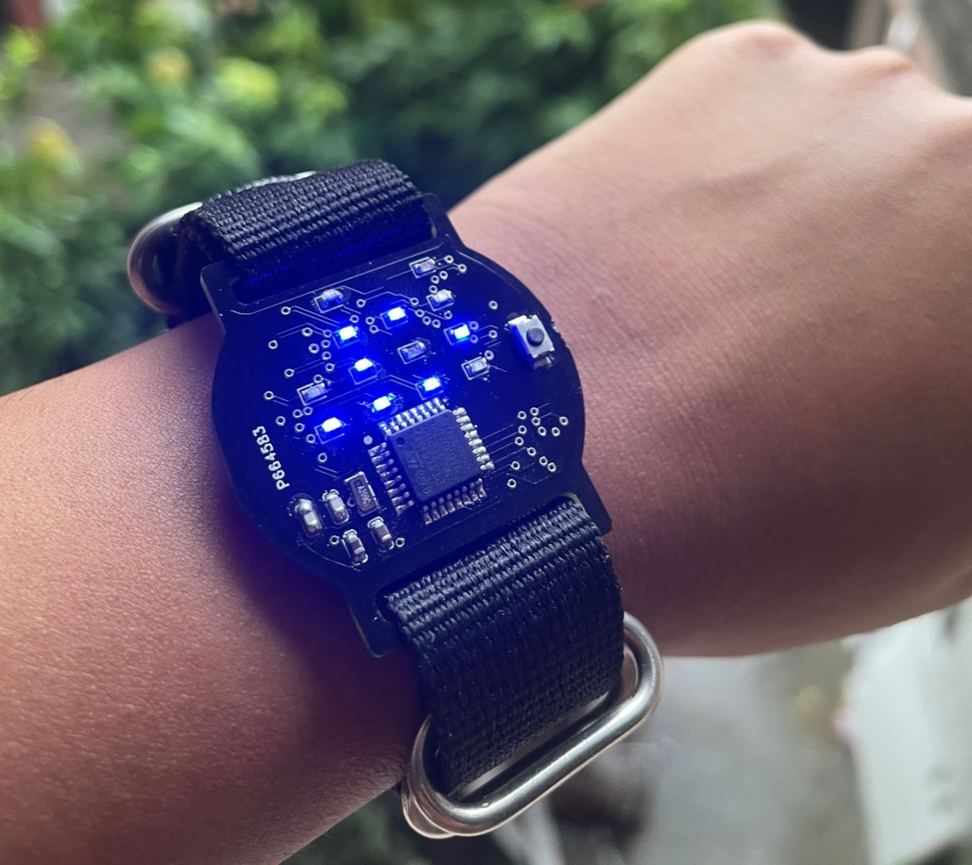
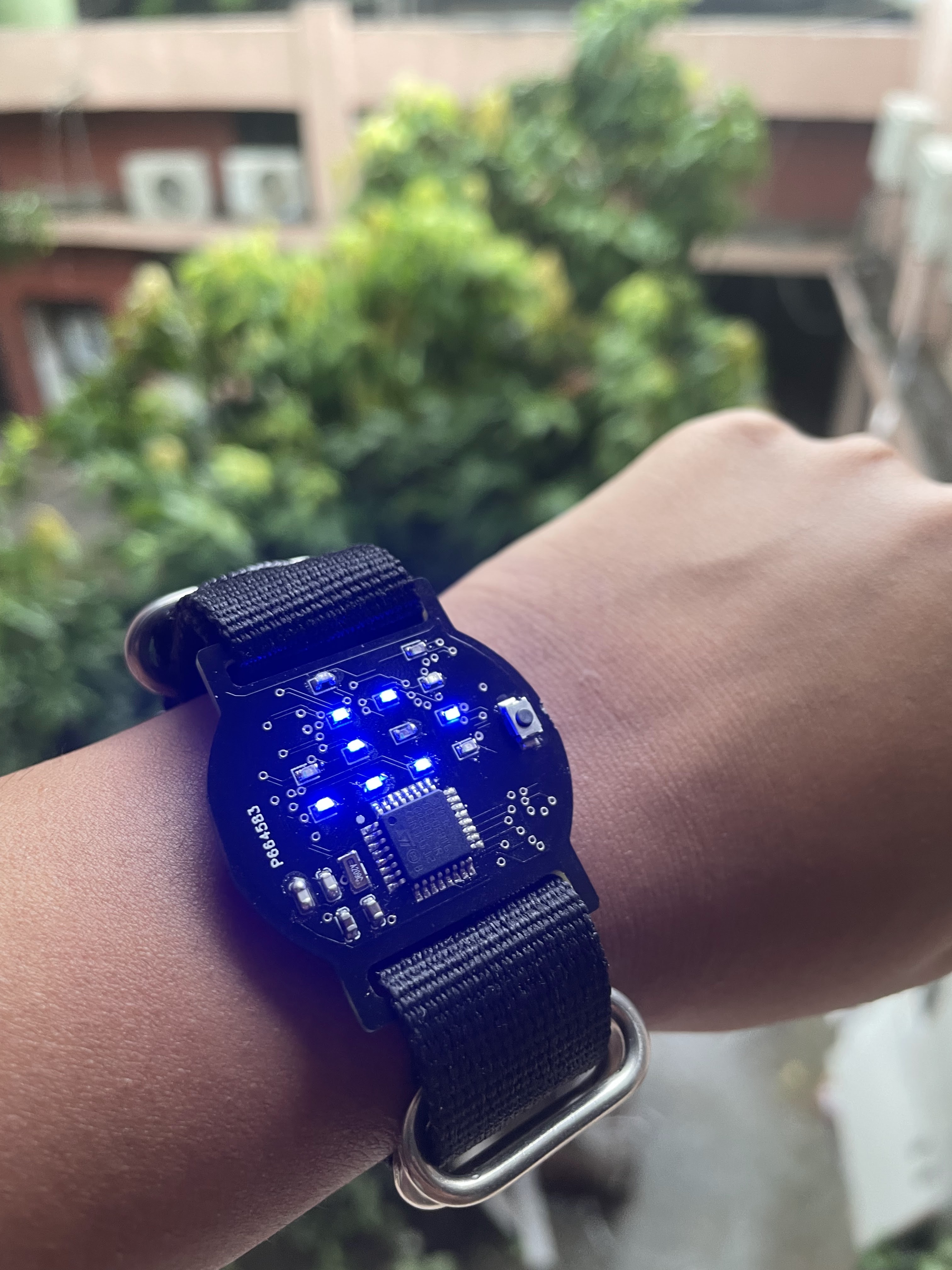
Really quick before we start, this is how you read the watch:

Throughout designing the watch and wearing it over the past two days, I’ve become quite accustomed to the format. It’s not that hard once you get used to it. And for me, the look offsets the work – beauty is pain, after all.
Yes, I know, technically, this isn’t a binary watch. It is a “base 10 but each digit is in binary” format. But that doesn’t have the same ring to it, haha.
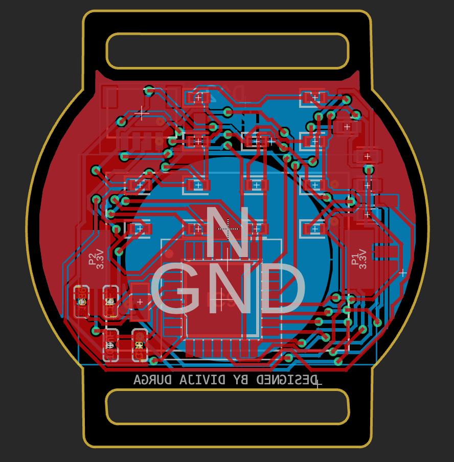
I started with designing the PCB. The capacitance values came from the recommendations given in the STM32G070KBT6 datasheet. The resistance came from this calculation:
Supply voltage = 3 V
Voltage across LED = 2.2 V
==> Voltage across resistor = 0.8V
Desired current = 0.02 A
==> Value of resistance = V/ I= 0.8/ 0.02= 40 ohms. We were out of 40R, so I ended up using 20R. A bit brighter than I had calculated for.
Initially, I planned on using an Atmega328p chip with an external DS3231 Real-time clock (RTC) IC, so I designed a PCB in Kicad with these components. I also used 1206-size LEDs, caps, and resistors because I was planning to hand-solder these.

I was advised to redesign the watch using an STM32 chip because it can function on lower voltages. We had the STM32G070KBT6 in the inventory, so I went with it. I changed some other components to match those in inventory.

I added a 1 mm Qwiic connector to upload code via SWD. I should have added a connector for serial communication too, because not having Serial.prints() made debugging very hard. I used special configurations of the LED matrix for debugging.
The Code
I wrote the code using the Arduino IDE and uploaded it using STM32CubeProgrammer.
When writing the firmware I ran into an issue. I didn’t want to set the time of the watch to compile time in setup(). This would be convenient when you upload the firmware; the watch would be accurate. But if the RTC lost power, say because you are changing batteries, the watch would again reset to a time like 2:39, or whenever you uploaded the code last. I wanted the watch to display the compile time when I uploaded the code and to reset to 00:00 every time the RTC lost power. This is purely a personal preference; I’d rather change a battery at a standardized time than at some random time contingent on when I flashed the firmware. Ideally, there should be a provision for resetting the time. I plan to incorporate that in future versions.
To achieve this, I used the EEPROM of the MCU. This memory stores data even when the MCU is powered off. So every time the time is set, I store a flag in the EEPROM. So, in subsequent firmware restarts, I check for this flag and reset the time only if this flag isn’t present. I need to clear the EEPROM every time before flashing the firmware, which is a bit inconvenient, but that is the method I have gone with for this watch version.


Another concern was that a CR2032 wouldn’t last long if it was used to power all 13 of my LEDs and my microcontroller. However, my microcontroller can operate in a low-power mode, with a special Arduino library to facilitate it. The Atmega328p and ESP32 also have similar libraries, so for those wanting to make this watch with alternate MCUs, definitely check them out.
I added an external tactile button. Every time it is pressed, the low-power mode is exited and the LEDs switch on to display the time.
Here is how the conversion works:
This just breaks up the time into the tens and ones.

This piece of code left shifts the binary representation and then accesses the least significant bit. Effectively, this code accesses each bit of the number from the right, one by one.
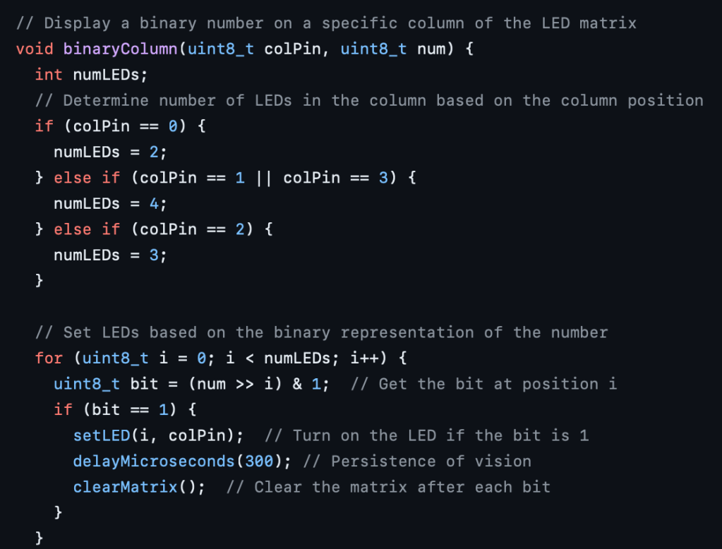
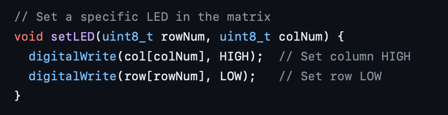
The function setLED() just translates to switching an LED at row x and column y by keeping the column at high and row at low as this creates a path for current to flow through that LED specifically. I had worked with LED matrices before but under the abstraction of Arduino libraries. This source helped me understand this: Explanation by Mika Tuupola
Each bit is displayed for 300 ms, and the persistence of vision makes it look like all the LEDs are on at once. Here is why that’s needed:
Let’s imagine that each LED can be represented by a pair of numbers for its row and column, denoted as (x, y). When we switch on LEDs at positions (1, 1) and (2, 3), it also causes LEDs at (1, 3) and (2, 1) to turn on because there are potential differences between row 1, column 3 and row 2, column 1. To prevent ghosting (unintended illumination of LEDs that should be off), we need to switch on the LEDs individually.
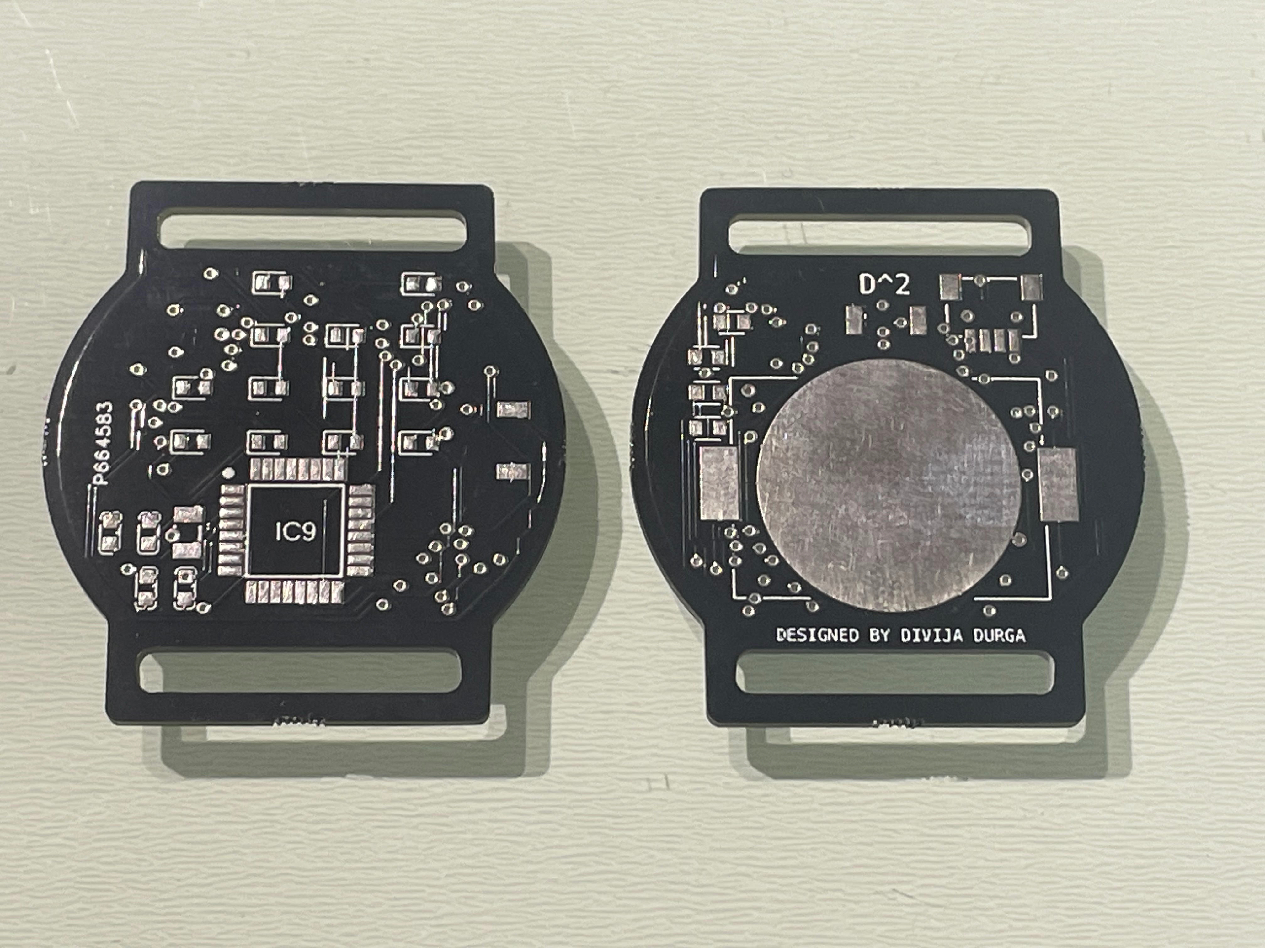
So far I’ve made two watches. Neither one of them works perfectly, but I think both of them are fixable. For the first one, I just messed up the soldering. There is a short I haven’t been able to locate. The second one works pretty well, but the crystal LSE circuit is a bit erratic. I added some code to display an “error” combination of LEDs so I know when the LSE fails. If it does start, there is a bit of a time drift. Although that can be managed by resetting the watch at midnight, that’s not a good solution. I suspect the reason is my capacitance values. I just went with 1 pF value (for a reason I don’t even remember), but I found this equation for calculating the capacitance values:

image source: AN2867 Application note: Guidelines for oscillator design on STM8AF/AL/S and STM32 MCUs/MPUs
I found that the external capacitors needed to be 15 pF, assuming a standard stray capacitance value of 5 pF.
I’ve tried out the RTC section of the code on an ST Nucleo board, and it works perfectly, so I’m pretty sure my issue is in the hardware. Hopefully, it gets fixed in the next board I solder. Otherwise, resetting the watch every midnight it is!
All in all, I’m pretty happy with how this turned out. Still a lot of work to be done, but I’ve been having lots of fun so far. The only downfall is that I don’t have access to IIT’s resources. But I’m planning on buying my components, and hopefully, some lab at Princeton will let me use their reflow oven.
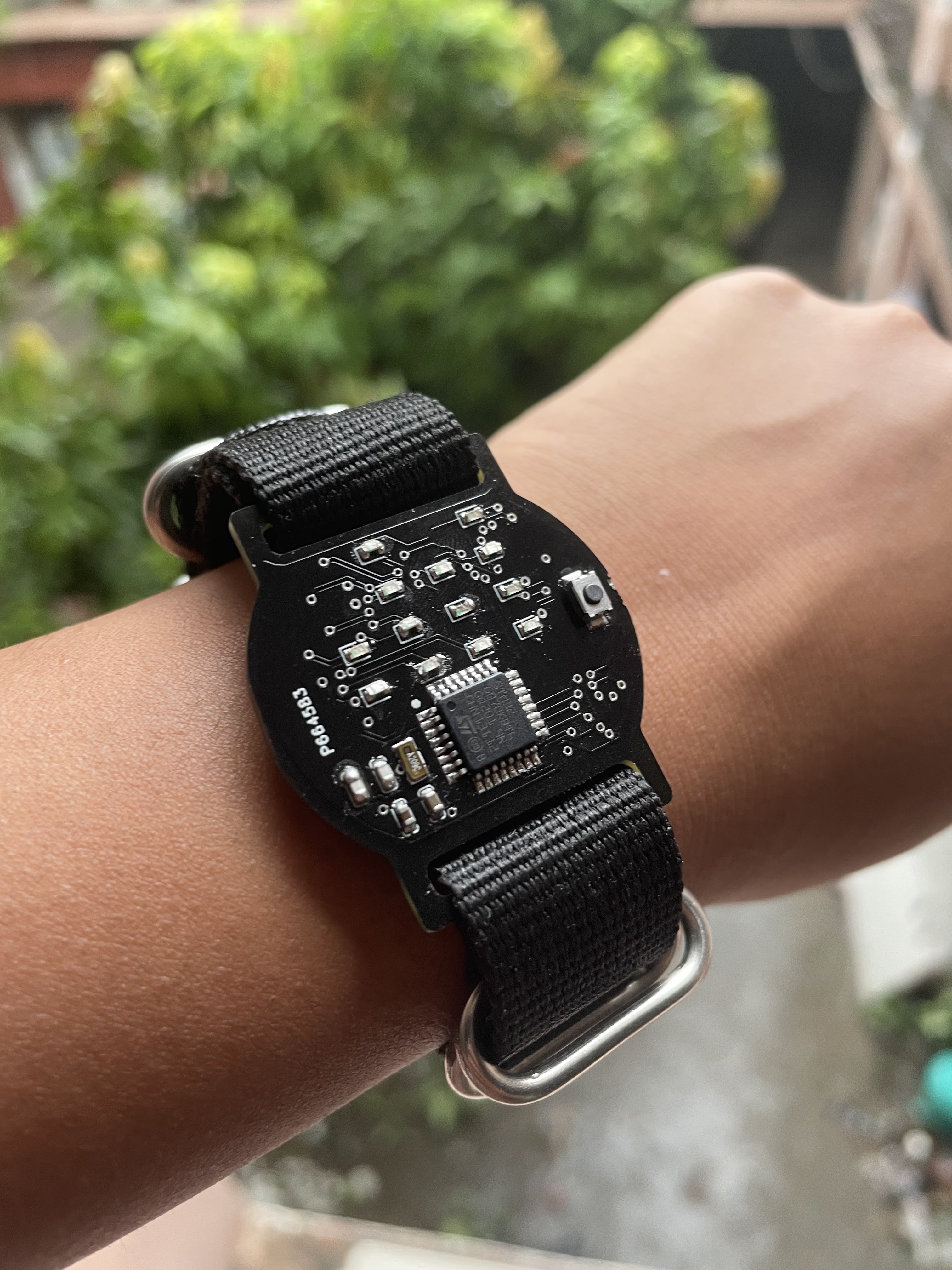
Making it Wearable
I found Nato straps online which are just single, continuous straps that you can thread through both strap openings of your watch. I chose these because I didn’t have to design anything overly complicated for the connection between the watch face and the strap. Also, they created a barrier between the skin and the metal battery holder on the bottom side of the PCB.

Leave a comment